Module 2
I delayed, and delayed, and delayed on starting the second module, for absolutely no good reason.
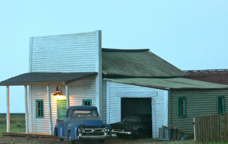
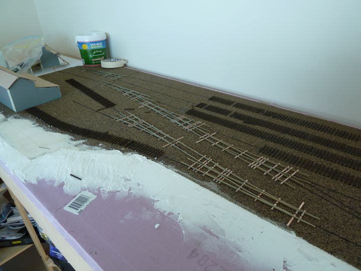
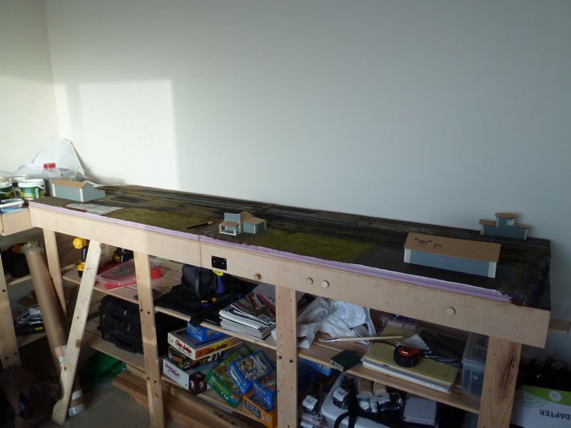
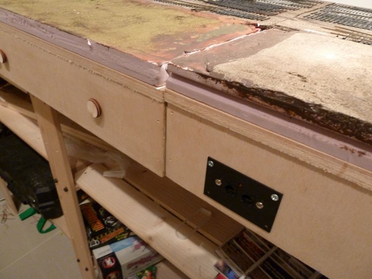
At this time, the first module was still under construction, but I'm nearing the limit of what I can do while it's on it's own — I need another module to join to the first so I can expand the track work.
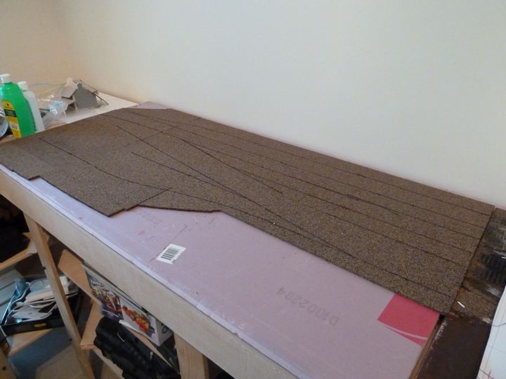
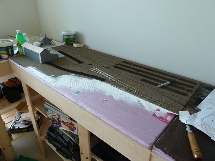
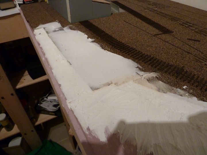
So I finally took the first step, and glued the foam to the plywood base. 24 hours of drying time, and voila!
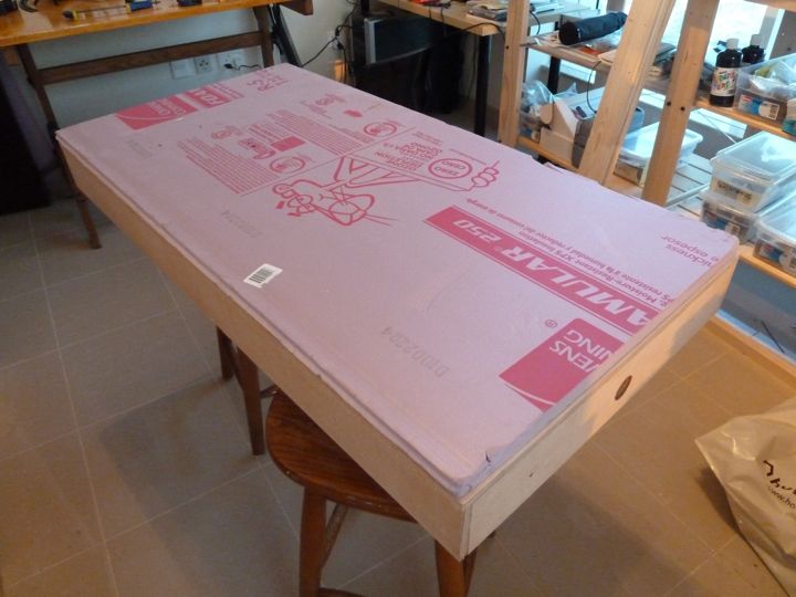
Sometimes, it's the smallest steps.....
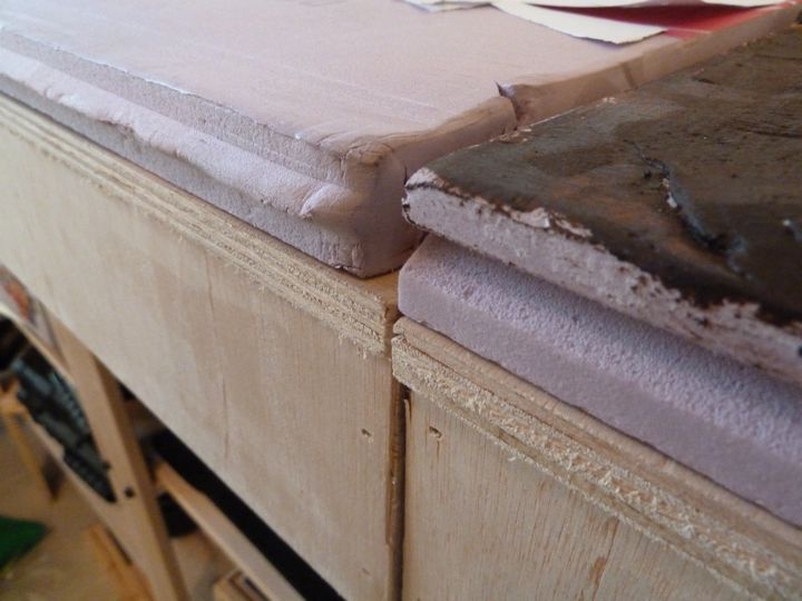
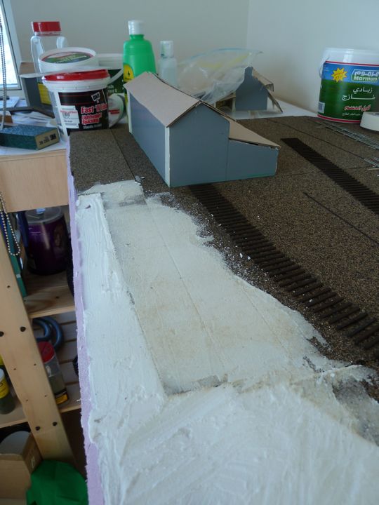
I stopped and considered a bit how I was going to deal with the gaps between the modules. I finally decided that it's going to depend on how big the gaps are - I didn't get clean cuts when I cut the foam, and while I'd like to replace it, getting the materials is such a PITA here, I have to live with it.
Once the majority of the track is down, the modules will be joined and fixed in place with each other - at that time, I may either try and find the gap filling foam in can, or just use loose material underneath a spackle surface. There shouldn't be a lot of movement as the plywood module base will be tight to it's neighbor.
Once that's down, than track goes across - note there are no joints happening at any time the plywood or foam meet.
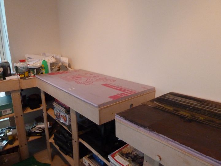
With the foam attached to the plywood, I was able to move forward.
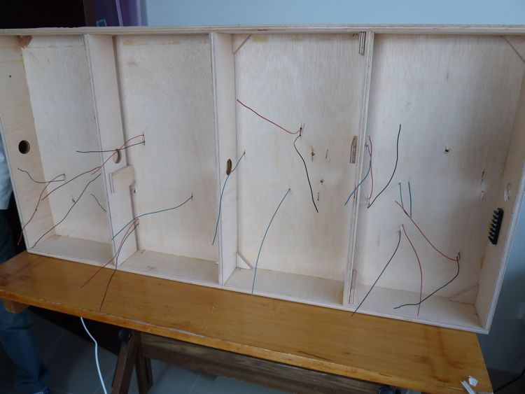
First was lining up the module tops. I decided to match up the plywood top instead of the module face (due to what clearly are some inaccuracies in their construction), and clamped the first module to the second tightly.
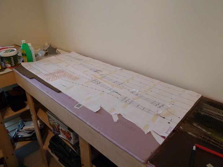
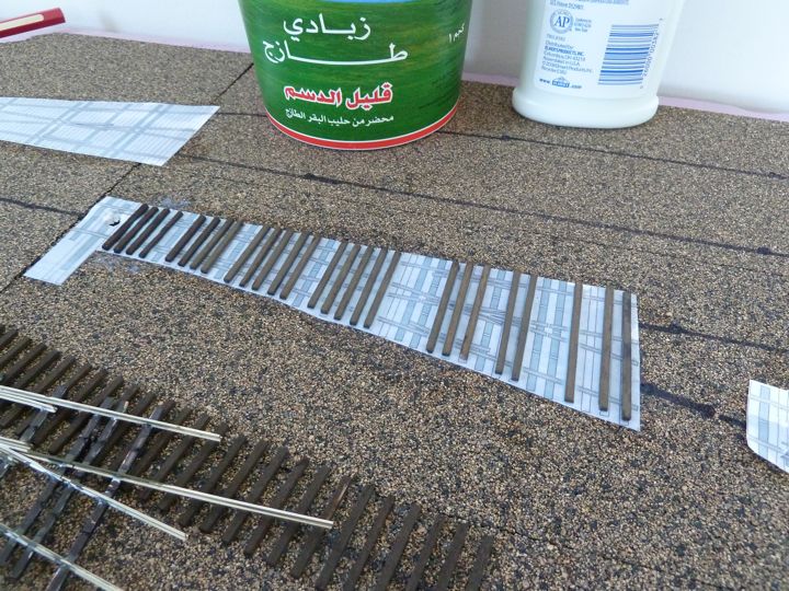
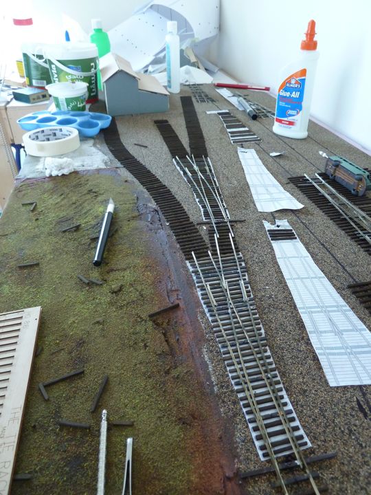
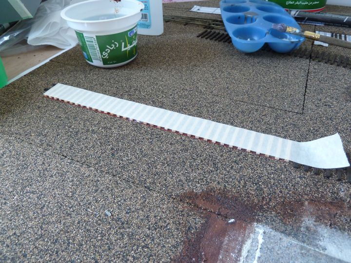
Next, I brought in the paper template for the second module. Hold on, this looks like it actually lines up!
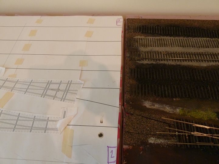
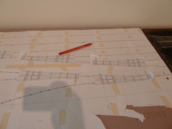
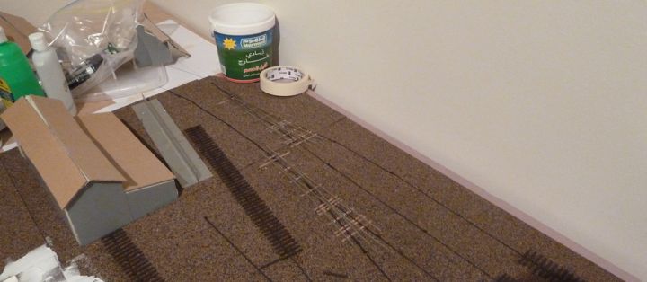
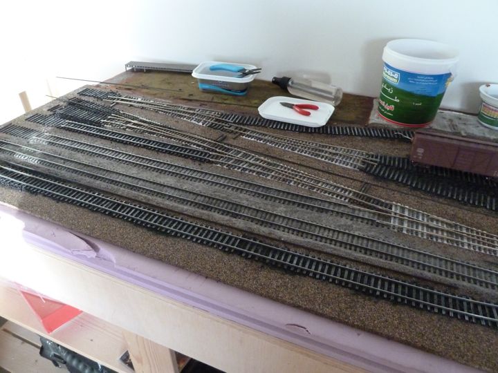
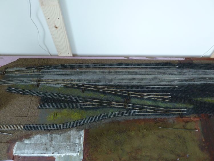
I than went through and punched out the center lines of each track with a large wax pencil. This allows me to punch through the paper to the foam. Other folks have different ways of transferring the track plan to the layout, but for me this is easy - and will have to be done again once the cork is down. For now, it provides a great guide on to where I need to apply the cork roadbed.
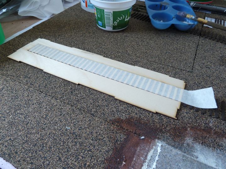
Before I pulled up the paper though, I test fit a couple of sheets.
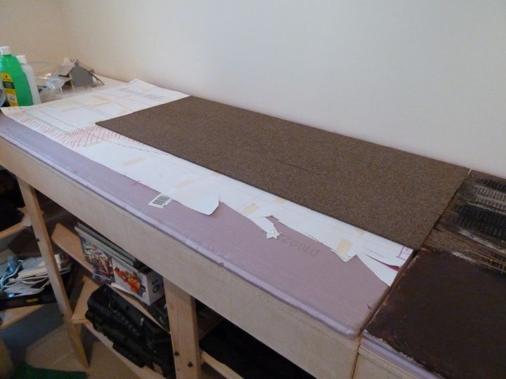
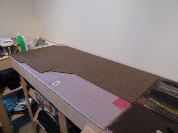
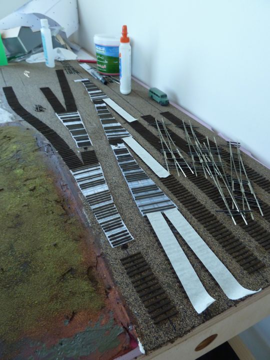
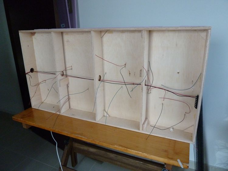
Finally it was down and drying. Next up, was to re-transfer the plan again, this time on top of the cork.
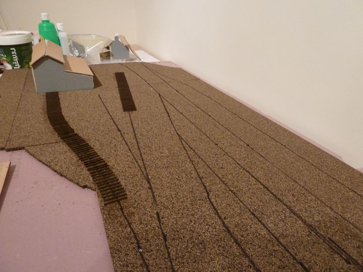
Progress! With the cork down and dried, I transferred the track plan to the cork itself. I do this by using a sharpie in the same holes I punched through with the pencil, and than connecting the resulting dots.
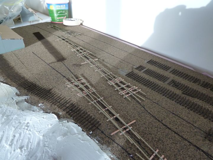
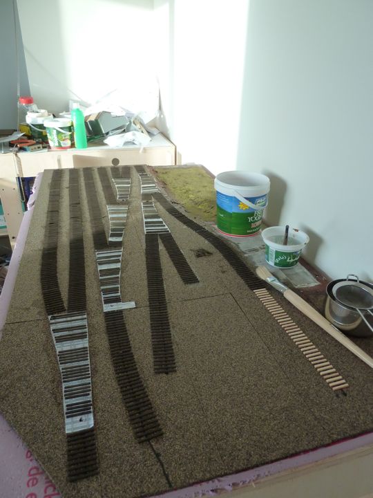
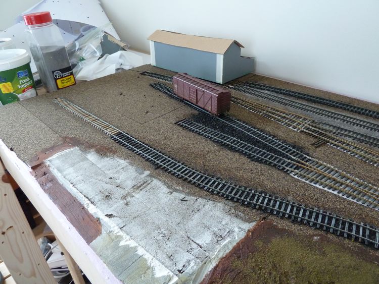
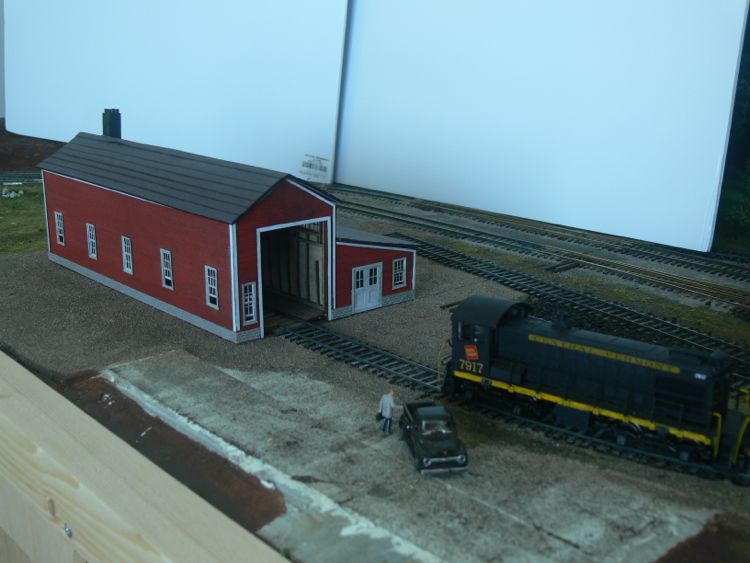
I was struck again at how useful taking the time to make the mock up buildings. With the track lines in place, I had enough time to start putting down some ties, and being able to size up the engine house at this stage was very useful.
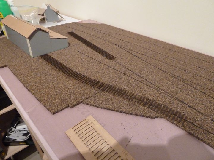
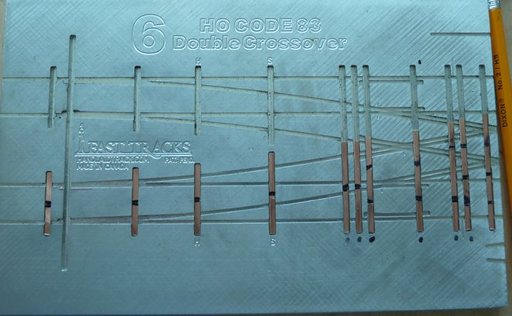
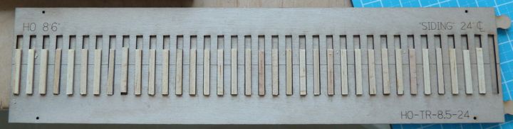
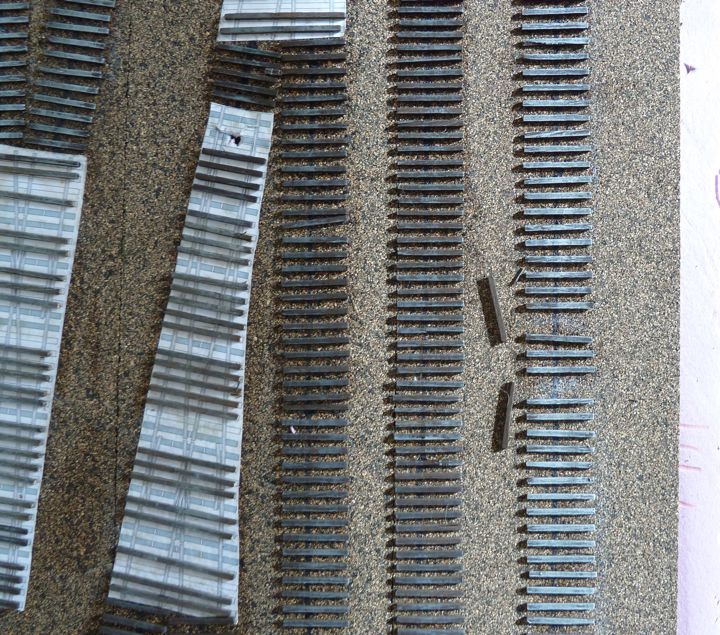
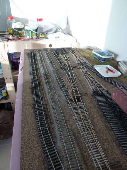
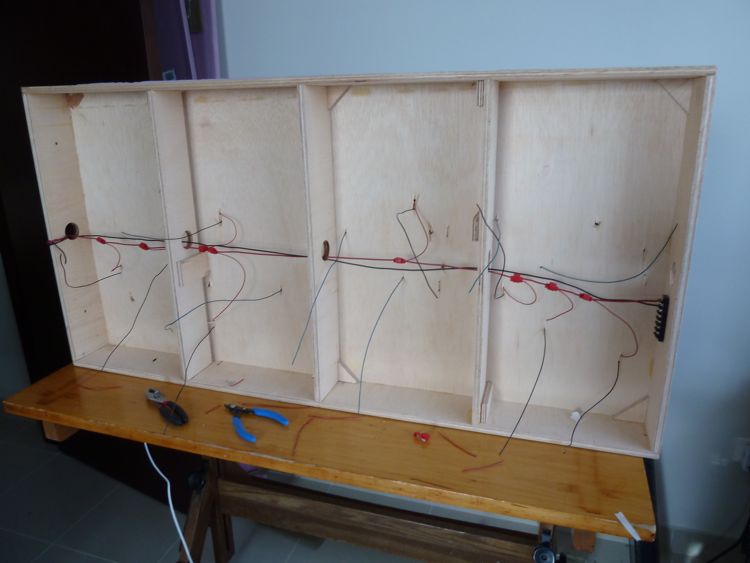
Besides only having a little time to lay ties, I needed to build the turnouts first for this module. I have five to build, so that's going to take me a little bit.....time to break out the Fast Tracks jigs!
More ties went in, and I got two turnouts fully assembled, gapped, and ready to go.
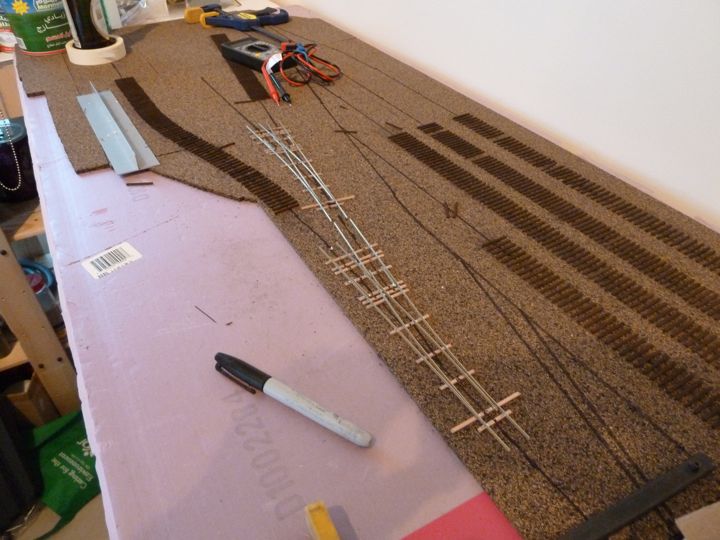
I had actually forgotten how much fun it is to build these turnouts. That's a good thing, as I need another 4 for this section alone.
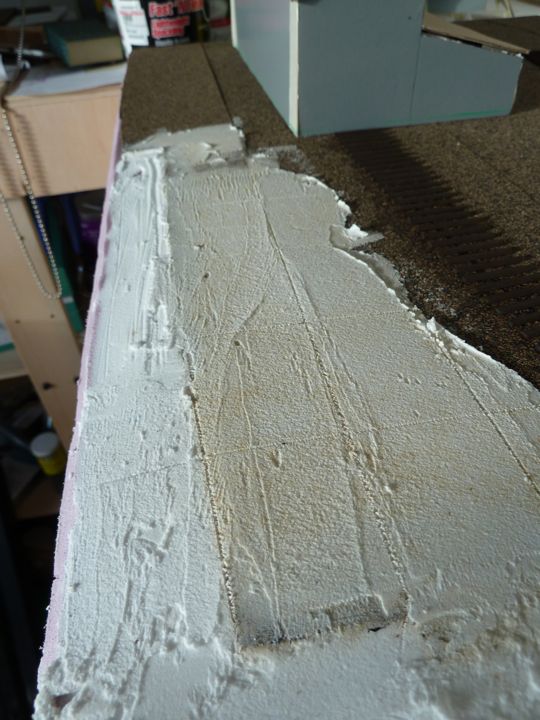
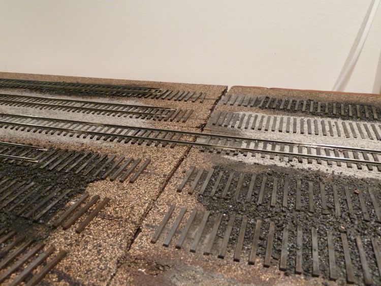
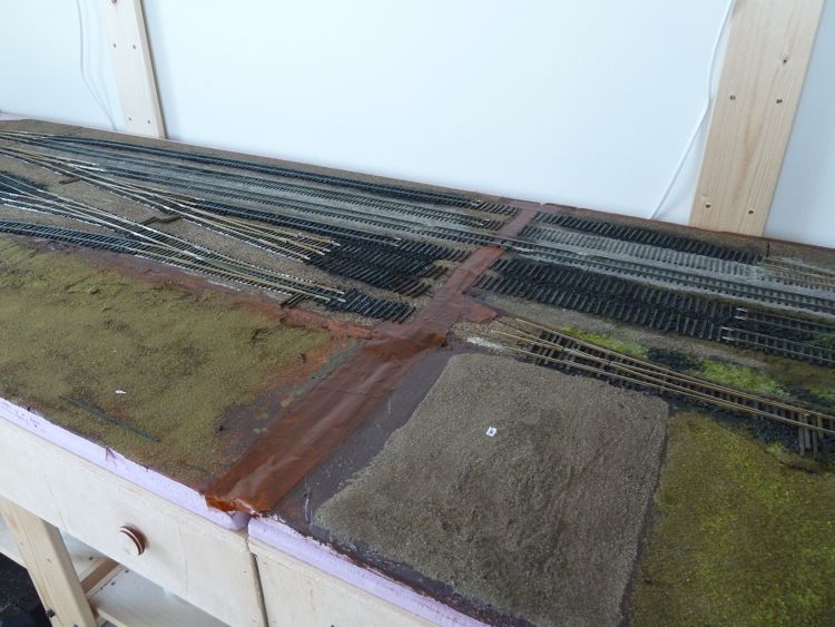
I had forgotten to slope the edge of the cork, and I took care of the first coat of that.
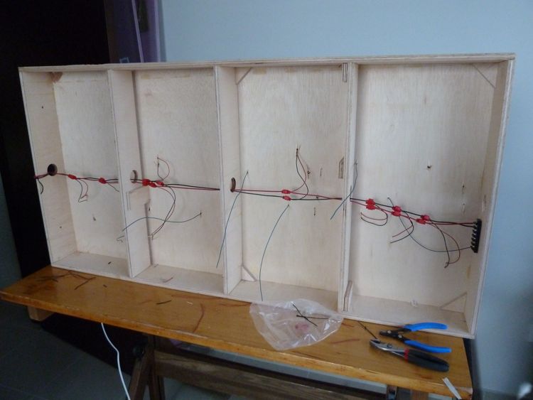
That didn't seem like much progress, but I did get another two (this time code 83) turnouts made, gapped, tested, and washed.
For those that are interested, it's not a big deal to make a single turnout from the double crossover template; I measure the length of ties from a printed copy of the standard template and go from there.
There are also two extra ties in this jig vs a single turnout, I go ahead and add them in with the proper gaps. In the photo below, the black marks on the ties are already cut gaps (I read somewhere that sharpie repels flux, so I go ahead and mark up all of my gaps with it, just in case I'm really sloppy).
Just finishing up some soldering.
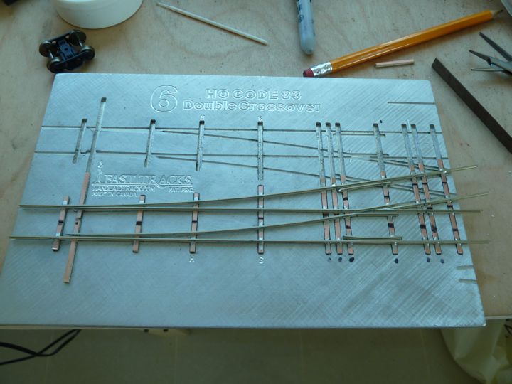
And the finished turnout.
Only two more no. 6 turnouts to go for Module 2.
Note that with the crossover jig, you don't need the extra ties — the turnout is fine without them. The two extras based on my picture are the first and seventh from the right (diverging end) of the turnout.
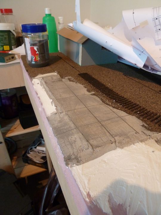
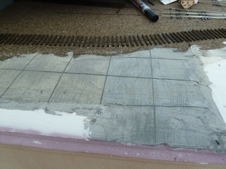
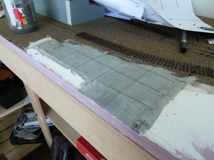
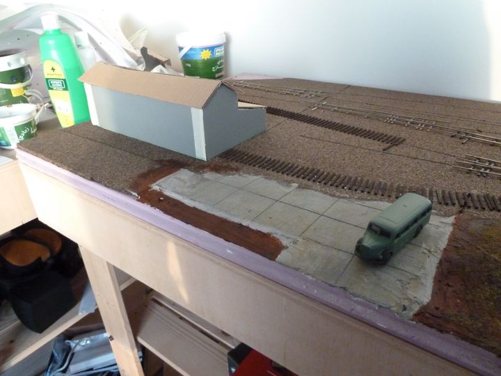
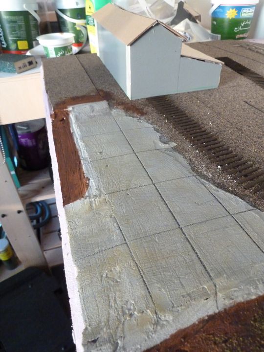
More meager efforts included some more plaster work near the engine house. I'm intending on trying to "concrete" the driveway; so here is the first coat of plaster down.
and I think I'm going to move this back turnout farther up - it wasn't going to be on the edge of the module, but I think that I will still be happier with it moved farther in.
Another turnout is also in the jig, with the ties cut, and a few of the rails sorted out.
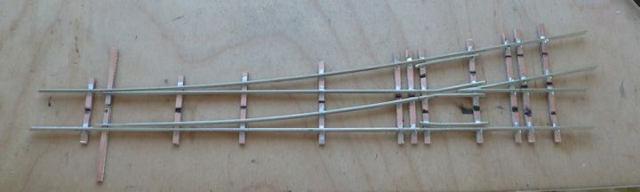
I got that turnout finished - it's amazing how fast these go together as compared to the double crossover!
I also cut expansion cracks into the concrete. I think I need to sand the surface lightly, and possibly redo the entire area, but we will see after the sanding. I want rough, worn concrete, but this may be too much.
The last turnout was completed.
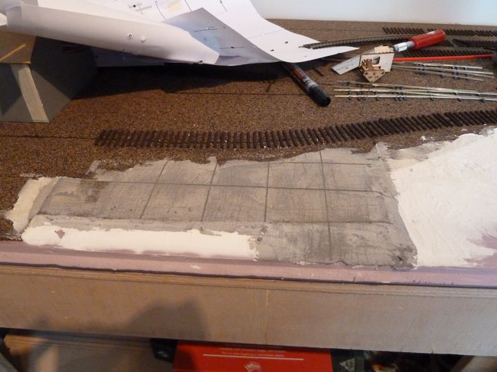
And another shot of the driveway...it looks better, but I'm still not satisfied with this.
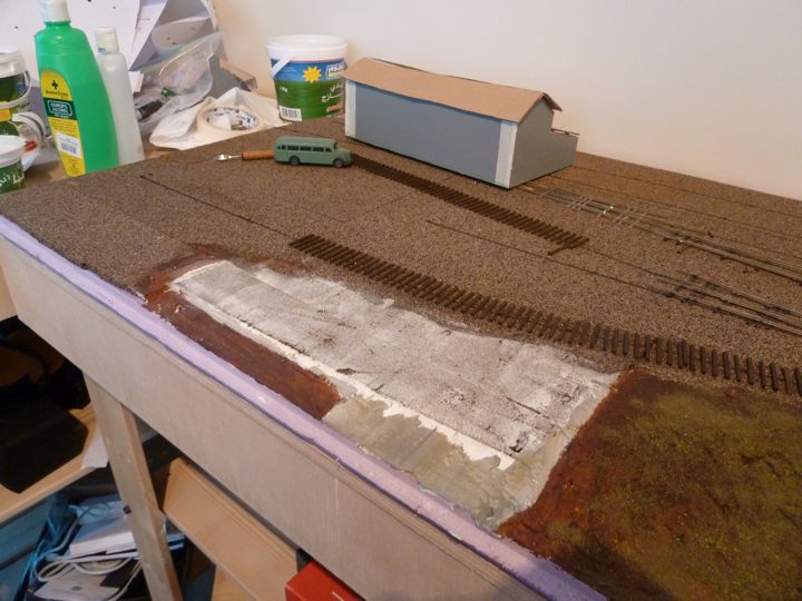
With the driveway sanded a bit, I went ahead and put a coat of Woodland Scenics Slate Gray color wash over the area. Here are the results.
I still wasn't sold on it.....the expansion cracks came out well, and I may be able to turn it around with following coats of dry brushed lighter grays.....but I'm just not sold on how it looks.
If you're wondering about the non-square edges, I'm looking for the effect where cinders and weeds have heavily overgrown the sides.
I had time to hit the pad with a light over paint / heavy dry brush of Poly Scale light gray primer. In the picture below, the pieces to the right have had the light gray treatment.
And with the whole pad done.
I decided (while the brush was wet with paint from working on the first module) to paint the rest of the front the brown color I've been using, mostly to hide the pink foam.
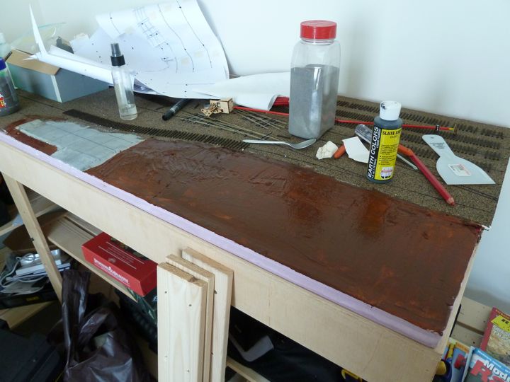
and, of course, being unable to stop there, decided that while the brown paint was drying, I might as well as hit the majority of it with the scenic underlayment I'm trying to use.
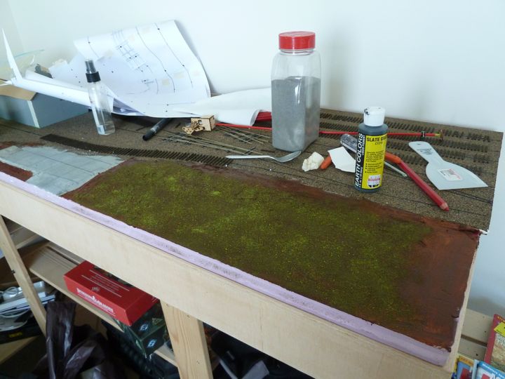
So now there's no rails on this yet, but turf!
I use Woodland Scenics fine turf "earth" under a dusting of summer lawn mix from Scenic Express for this base coat/underlayment.
I got to the third color, this time I used a very light dry brush of Poly Scale Depot Buff over the pad.
I still don't know if I'm that satisfied......but I may go with it for now. Due to it's location, tearing it out later if I'm still not happy shouldn't be a big deal. I was going to black ink wash this, but I'm thinking the recesses need less definition, not more.....
And than I ripped it out .
maybe I'm crazy, but I wasn't happy with it, and a light sanding wouldn't tighten up the expansion cracks. I'm going to pause a bit before going back into the pad.
Which meant I could get started on the track work!
There was a tip in Model Railroader on using templates right on the bench work, and I decided it maybe worth a try for me and putting down the non-PC ties.
So I cut up a bunch of appropriate Fast Tracks templates for my turnouts, and got them lined up with the track centers and throw bar holes I had drilled.
I than painted them with white glue and water, both sides, to get them to stick to the cork.
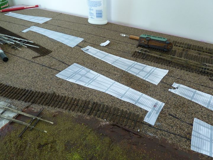
With the glue mixture still very wet, I used another template to measure ties, cutting them one by one and applying them directly to the top of the template.
With a turnout on for sizing, if this works, you can see how it makes the spacing nice and even.
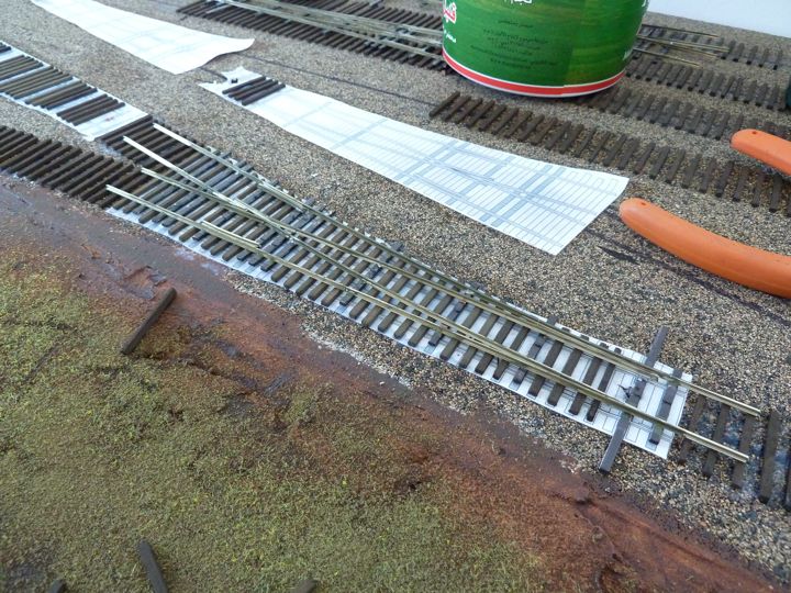
I went ahead and did three as a test. Knowing where the turnout ties ended, also allowed me to fill in some gaps along on the near side sidings (the engine house lead, RIP track and van track).
The turnout tie templates turned out ok - in fact, they're really pretty good! I cut away the tail that covered the throw hole in the module.
Satisfied with that, I went ahead and did the next two that I can reach (I'll go ahead and flip the module around to get the back side once this side dries).
This squares away a lot of the tie placement for this module, as mentioned, a quick flip, and I should be able to finish up the rest of it pretty quickly.
I was reminded that I need to get the inside track that fits in the Branchline Single Stall Engine house sorted out. I dug the box off the shelf, and after taking it apart, found that it has a plywood foundation with a cut out around the interior track.
The only problem is the bare ties I have for this are too long...
So it was time to break out the Chopper II from Micro Mark that I purchased before I left the US. I have never used it, and this seemed like a perfect application.
Unfortunately for me, mine has significant side to side play that I only identified after making my first cut, and finding it short. I can't tighten the screws any more, I simply over came it by pulling tight to one side as I cut for consistency. It did make short work of my tie trimmings, and it's pretty damn accurate for having as much slop as it does. I sincerely hope that it's only mine that has this, I'd return it for another were the postage not an inhibitor. I may take it apart later and try to rebuild it.
I filled my Fast Tracks tie jig with them, and lined them up on one edge prior to installation.
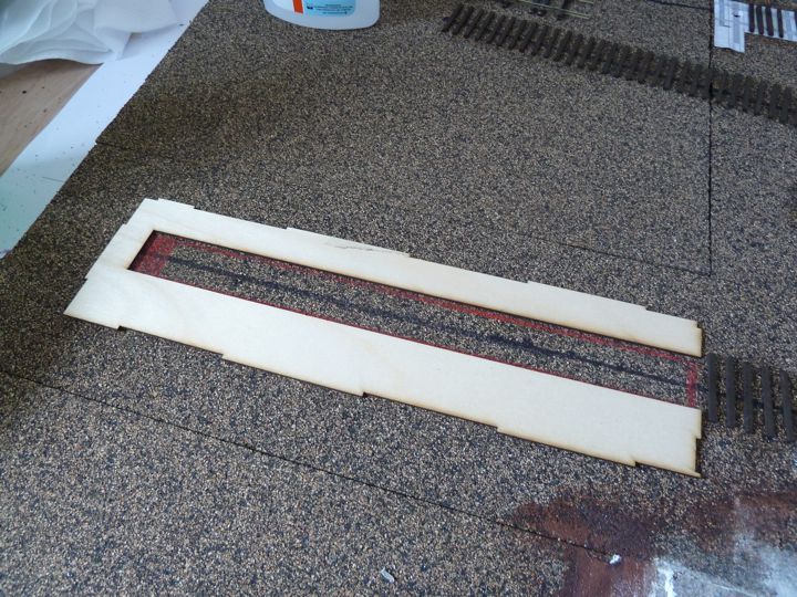
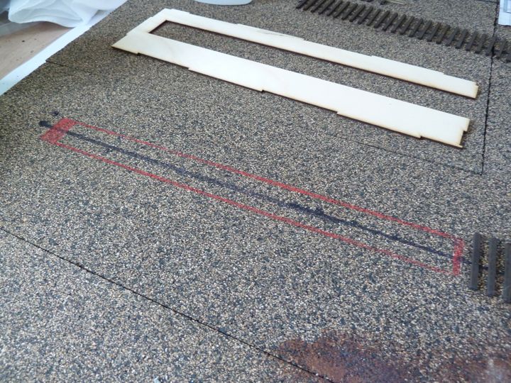
I used the plywood base as a template, and marked out the area in between with red pencil.
Some glue....
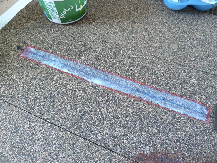
And down go the ties.
I put the plywood back down as a test, and it looks pretty darn good.
Note that there is no inspection pit for this model, mostly for the following reasons.
- There wasn't a single stall engine house in Montpelier Jct. I'm just making it up.
- The main CV shops were located about 70 miles north where they could and did do complete engine rebuilds; 50 miles south in WRJ there was also a sizable engine facility. A basic shed is sufficient for a small branch line in the middle.
- Besides rain, Vermont get a fair amount of winter weather, from October until April. A covered work facility, even if imperfect, is a damn site better than without.
- I can always go back later and add if if I wish, you may notice this is on one inch foam. Making a pit is an option I'm reserving for a much longer time down the road, once I have trains operational.
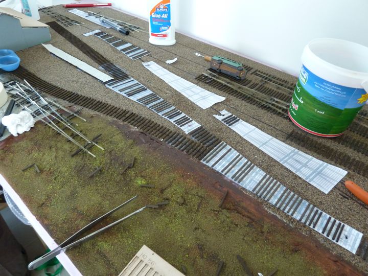
The tie work is now finished on this module. It gets flipped around for access to the back side, and voila.
The turnout templates used in this manner are real time savers, for the moment, I'd certainly recommend this method.
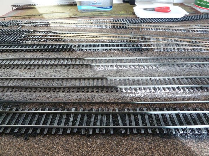
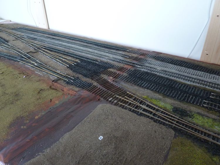
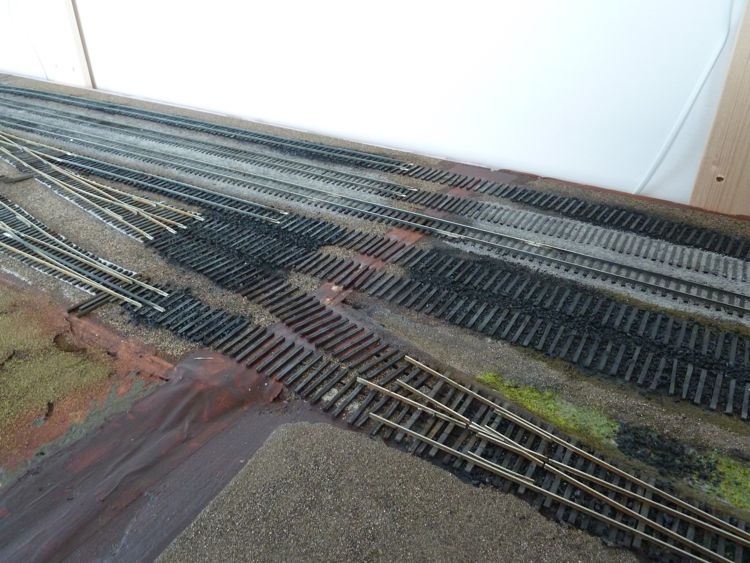
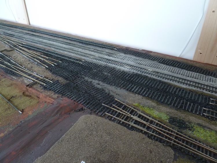
I "seasoned" the ties with a couple of shades of gray paint prior to ballasting.
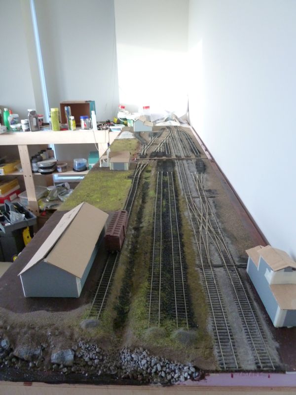
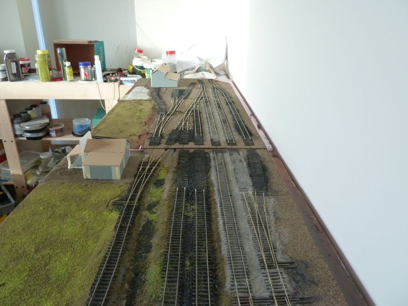
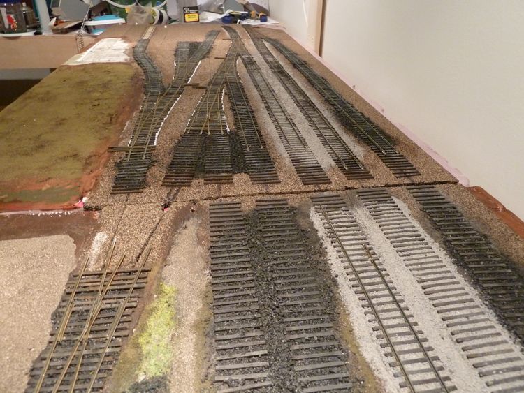
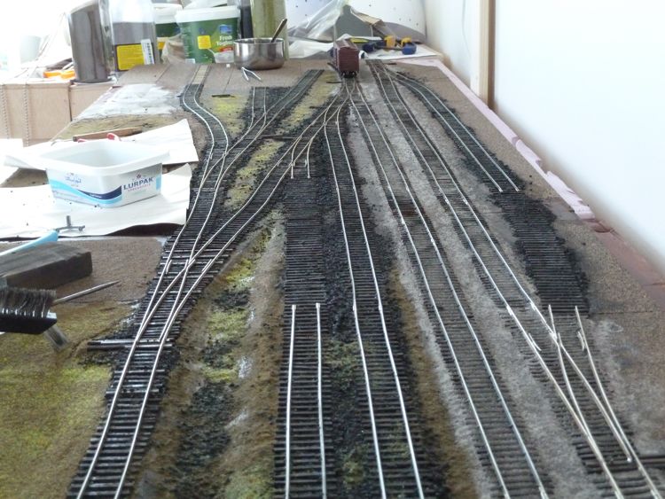
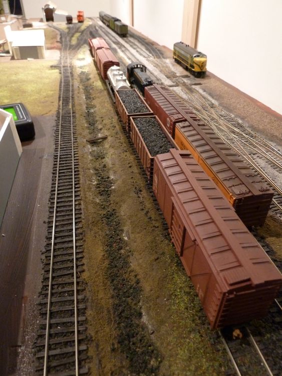
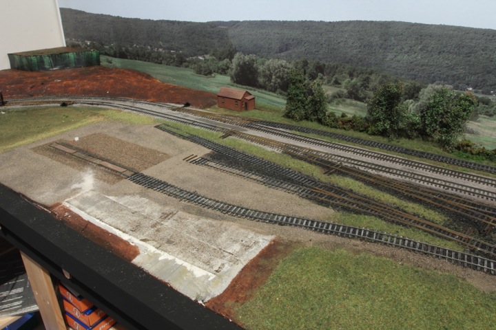
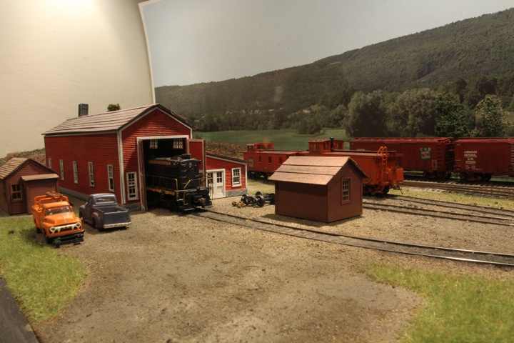
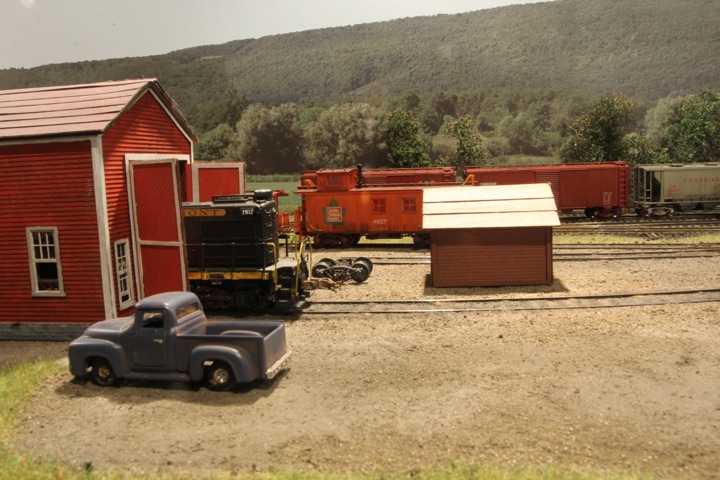
Here's a better shot of how the ties look. From right to left, that's a siding, the main, the branch line, and than yard tracks.
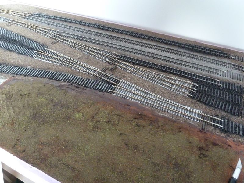
The track gangs were back to work and put some iron down on this module.
Four of the six turnouts are in place and spiked down with their frog feeders in place, and I was able to run the siding and the mainline (including feeders) along the back of the module.
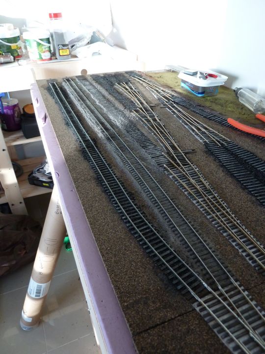
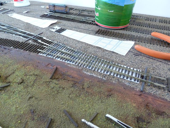
Front to back, the rear siding, mainline, branch line, and yard tracks. The light is deceiving, the rear siding is code 70, and the main 83. I was going to try and use 55 on the siding, but was too afraid to get a smooth transition from the 83 to 55.
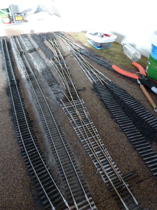
I was able to get the next two tracks wired up and put down, the branch line and the first of the yard tracks. It's almost ready to flip around to the front, and complete the service tracks.
From the the front of the picture (which is the back side of the module) siding track (c70), mainline (c83), branch line/passing siding (c83), yard track (c70).
I put down the last piece of track on the back, and than flipped the module around and got the two remaining switches installed in their permanent locations. I should mention that I "fix" my fast tracks turnouts to the roadbed the same way as normal rail - with spikes along the rail edge. I normally spike heavily near the throw bar, along two ties in the center (I spike the interior rails as well), and finally on the outside end (both routes). I try to always spike next to a PC tie if possible, just in case.
So there's just the three small leads to put in place, than the track is done, rig up some bullfrogs, and it's ready to join the first one.... I wonder how that will look.
looks like things should line up nicely....
Hand Laid Track
So why hand lay track?
I'm not going to claim that hand laying is better than other methods. Nor will I claim is that it is less expensive (in fact, the costs do add up pretty quickly).
What I will claim is that I have really come to enjoy the process. I love the fact that I have complete control, of the track, it makes tweaks and adjustments a whole lot easier in my mind than working with commercial products. I also think it looks good (I do think wood looks more like wood than plastic), even though there are not tie plates.
I do recommend folks give it a try and decide for themselves. I was interested in trying it, and once I did, I was hooked.
I'm also very satisfied with the Fast Tracks system. I enjoy that construction process, and the fact that you get very solid turnouts in a short time is very satisfying, and has helped encourage me to continue.
I fully understand how the start up costs of a Fast Track's jig can be prohibitive, and it should be factored into the decision process.
For myself, I calculated my value based on the average price of the Peco turnouts I was purchasing ($15.00 each). I bought two jigs, a number 5 and a number 6 (the former from FT as part of the starter kit, the latter off of eBay for $100). As there is on average what I estimate to be around $3 in other materials per turnout (ties, rail, solder, flux), I place the amortization cost at around 15 turnouts per jig.
On my second chainsaw, I created 7 number 6 turnouts, and 8 number 5's. Considering just the cost of the jig and the building materials, that's $17.30 a turnout.
I sold my no 6. jig back on eBay for the same price I bought it for, and purchased the crossover jig from FT for $150, increasing my overall cost investment by $50. On my current layout, I've already created another 8 no. six turnouts, for an overall average of $13 per turnout, and that doesn't include the double crossover (a code 83 HO scale double crossover is currently on sale at Walthers for $62 - a bargain, actually, based on the time it took me to make mine!).
I'm going on about this, as its clear there is a number of turnouts you need to make before you hit economical with the FT turnouts. I've broken even on my no. 6, and I will on the number five once I complete this layout.
Back to real work, I was able to get the track work on this module actually completed!
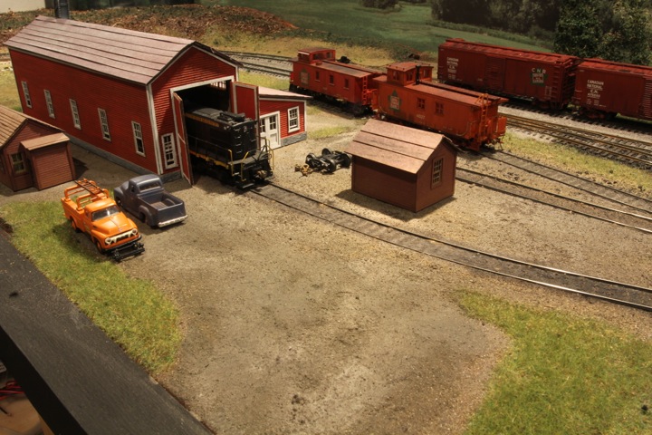
The last three sections were the ones in the service area - the Engine house, RIP, and van track.
I used code 55 rail for these three tracks - in part as a test, to see what it would be like to work with, transition to, and how my equipment might run on it.
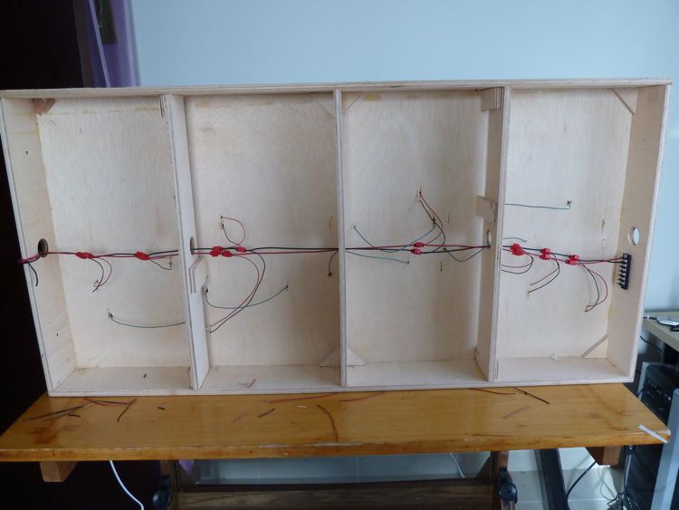
With the rail down, up came the module, and on it's side for wiring. I really have to say, being able to do this is a real pleasure, in comparison to crawling underneath.
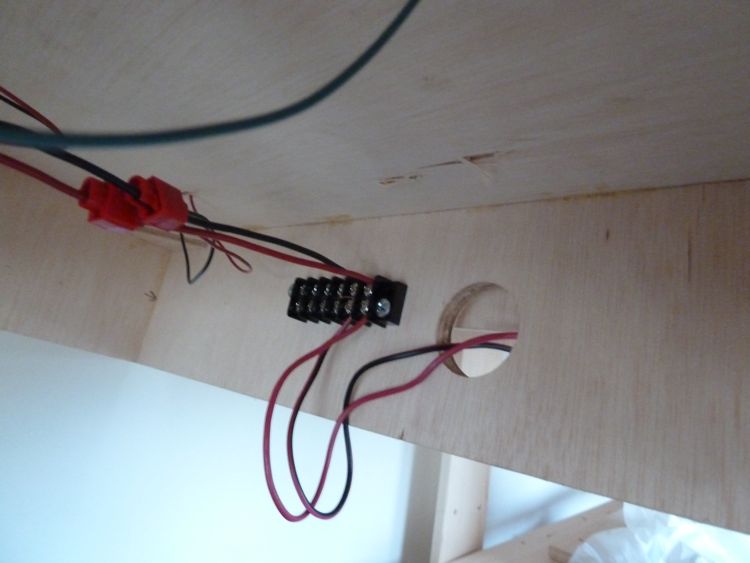
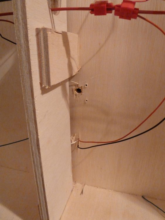
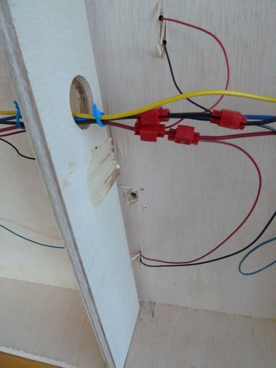
With it in a workable position, I first ran the bus lines. One end ties into the terminal strip (on the right), the other end is left loose to tie into the next modules terminal strip for the main connection.
Then the red wires were "suitcased" in.
And than the black.
Finally, the frog wires were pushed into the throw bar holes as a temporary step, just to tidy things up.
With that done, it wasn't too much effort to put it back, and connect the bus from module one. This is the only kind of work I have to do from below, using this system. Two wires per module that screw into place.
And once connected...
Power! I ran the loco through all the track work I could, and we're in business. I used a loose piece of wire to connect a rail from module one to it's corresponding rail from this module, and found one short - a simple mistake I made, easily rectified, and finding this made me very happy I went through that trouble before the two were bolted together.
I need to pull this module out, and put in six bullfrogs, and wire those up.....than these two modules can actually be joined up in their permanent configuration, and the joining rail put in place.
It's been a chorus of bullfrogs on this module, as the second module is almost frogged up!
5 done, and one to go......but this one will be doozie, due to it's near location to this riser.
It's either going to be removing the riser, or modifying the bullfrog......I can't decide which.
I decided to stop for a second, and put it on the benchwork, to check the work - and alarms bells began screaming.
I encountered a huge, unforeseen problem.
I decided to tear out the riser. It was just glued in, and came out pretty easily.
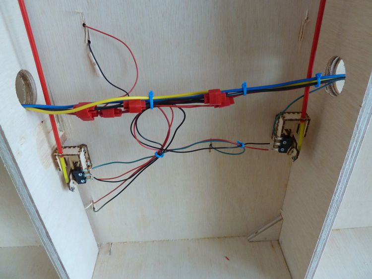
That left more than enough room for the bullfrog, and with that in place, it was time to get things wired up! This area is actually done from a wiring standpoint, so it was time to try and zip tie it all up a bit neater.
I was stuck for a day or two until an order from Micro Mark arrived, but I'm very close to being able to put this down and connect it (for good) to module one!
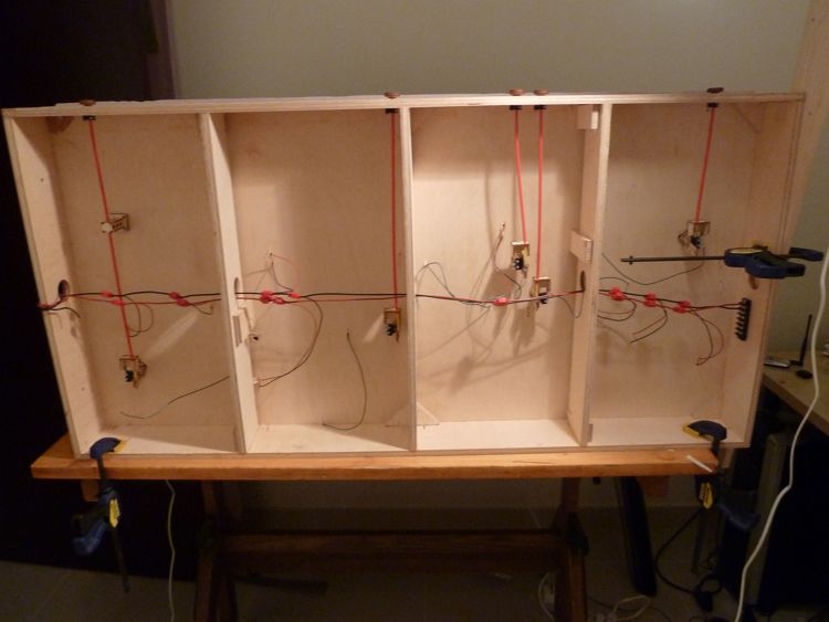
My order from Micro-Mark appeared, and I was able to finish wiring up the turnouts, and scenery lighting system.
Here is a shot of the finished underside of the right end of Module 2 - all turnouts are "hot", and the lighting bus added, and all wired synched up as neat as possible.
I have to say that during this step I've been living with my multi-meter. I started by connecting wires (loosely) to the switch on the bullfrog, and checking the frog polarity as I threw the switch, but came across a lot of problems - enough, that I got into the following routine.
- check switch itself with multimeter to see that it's working as designed
- check feeder wires against bus (terminal plate at the end) to ensure there is a solid connection
- check frog polarity as switch moves from trackside.
I found this to be a good process, as the new bullfrogs (the ones that use a spring and ball) mask the sound of the electrical switch, at least to my ears. Switches that I thought were being thrown were not, and I found myself adjusting a lot of them from the bottom side. Using the multimeter made these steps kinda foolproof.
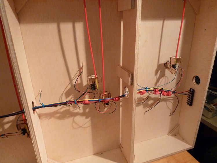
With the work under the module done, it was time to put it in place.
Believe it or not, these two modules are now mounted together! I clamped them in place, and drilled new holes for the through bolts.
You'll notice the wood doesn't' line up vertically - I'm not sure why, as all the material thicknesses used are the same. I didn't argue it though, and instead made sure the tie heights were level - in the end, I'm suspicious that's all that really matters.
They lined up ok - I'll need to figure out how to fill this gap in between.
Back came the multimeter, and with the electrical buses connected, I checked all rails against it's friend across the way. No problems.
Naturally, though, after all the time I've spent, I couldn't resist. I'll fill the other gaps later.
And video proof (at last) that it works!
Now to just seal that gap, and connect the rest.
Gotta cover the gap, and masking tape seems sufficient to cover the foam joints. Well, with the wood bolted together, why not?
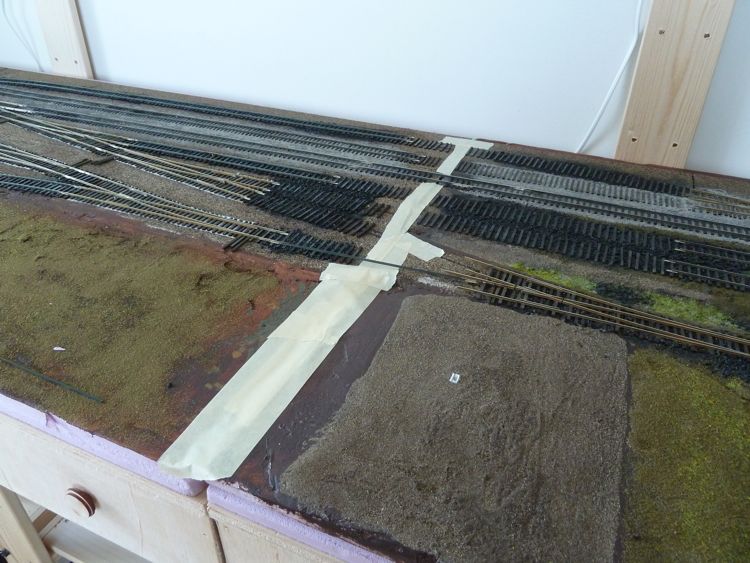
Then a coat of brown paint to help hide it.
Once that was dry, the ties were laid down.
And after drying overnight, they got weathered to match.
With that dry, ballast.
While I was ballasting this section, I went ahead and did the rest of the track (mostly turnouts) on the module.
Once all this dries overnight, I am hoping to get some more rail laid across the joint. In the meantime, I may get back to work on that building.
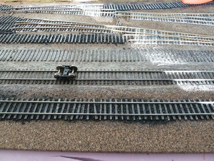
Most of my weekend's progress was finishing the track work between the two modules. Here it is with a few more tracks to go.
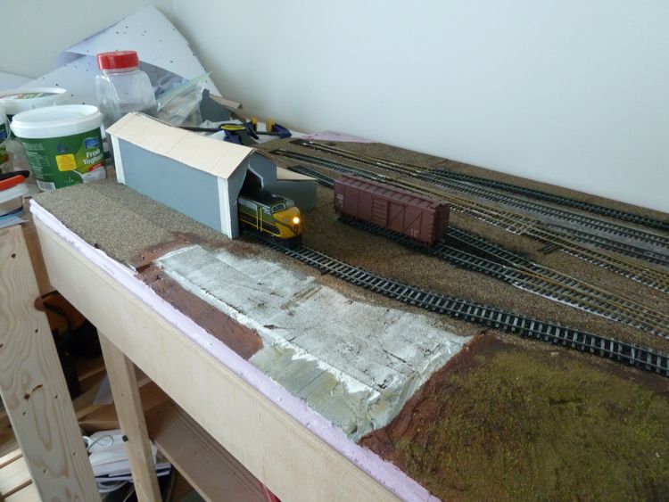
Once completed, I was able to break out some trains! Things, other than the 0-8-0, are working well.
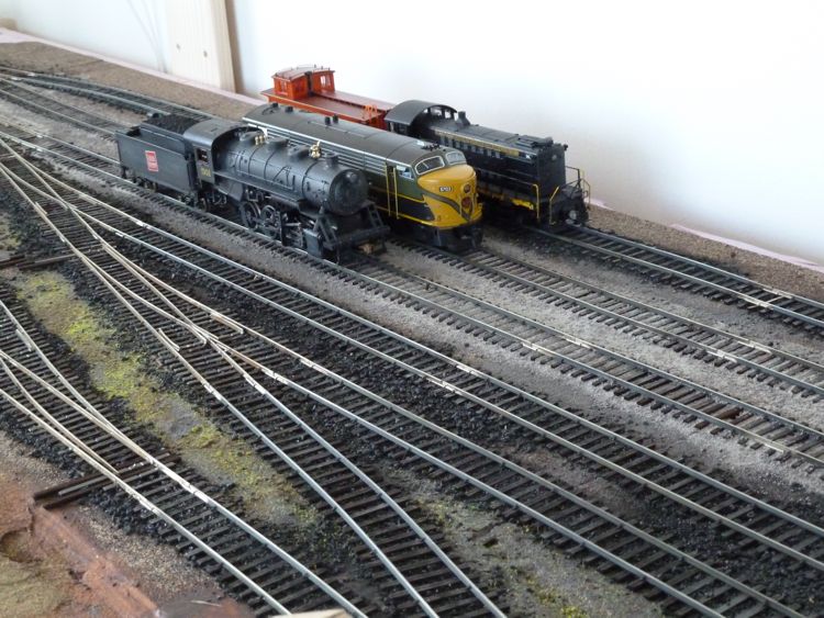
It's very nice to have something to operate on again....even though I don't have much of a switch lead, or a decent run around - yet.
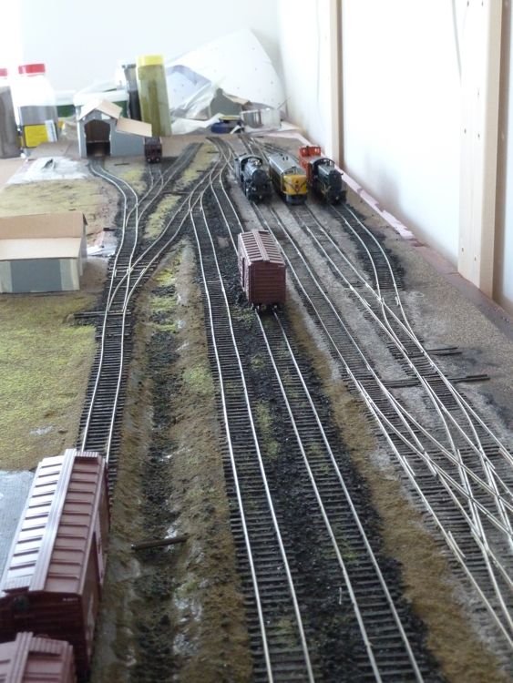
Almost time to get to work on the third module!
Just have to say, it's nice to run some trains - even if it's just back and forth!
The Engine House
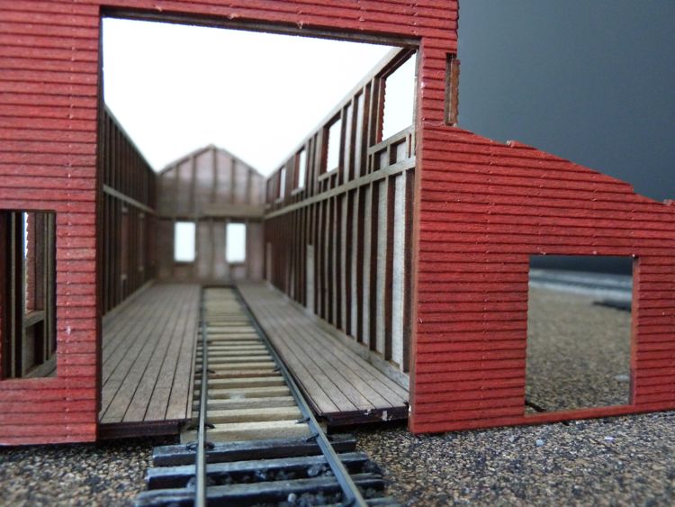
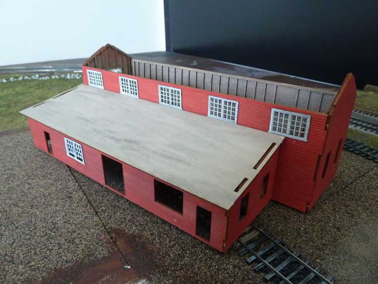
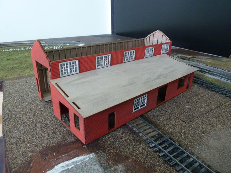
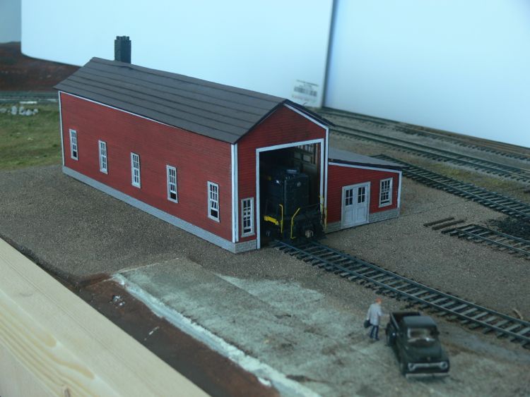
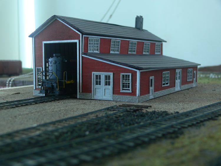
It was finally time to turn my attention to the building on this module, namely the Engine House.
The kit is the single stall engine house from Branchline (Laserart) based on a Central Vermont prototype. It's available from a variety of resellers, including Dallas Model Works (which is where I think I got mine...)
I don't know on the prototype, but I do know that the colors shown in the kit may not be the ones used. The CV had a penchant (thanks again to Marty McG. for this info) for a darker boxcar red with cream trim on it's buildings, but I like the red with white trim look, and I thought I'd just go with it.
For this model, I am working with a pastel crayon to color it. Before doing any coloring, each section was treated with an India ink/alcohol wash (top and right in the picture below).
The crayon was rubbed on loosely (middle), and than worked in with a dry paper towel (left).
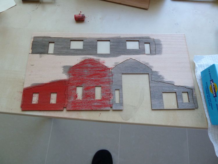
I discovered that this got a bit messy afterwards, and so I treated the pieces with dull coat. That sealed up the crayon nicely, and made the parts a bit less messy to work with.
The resulting color is nice, actually. Note that there is no weathering done to this at all yet, it's just the crayon and dull coat over the ink wash. (the interior walls and floor were also washed with the ink/alcohol mixture)
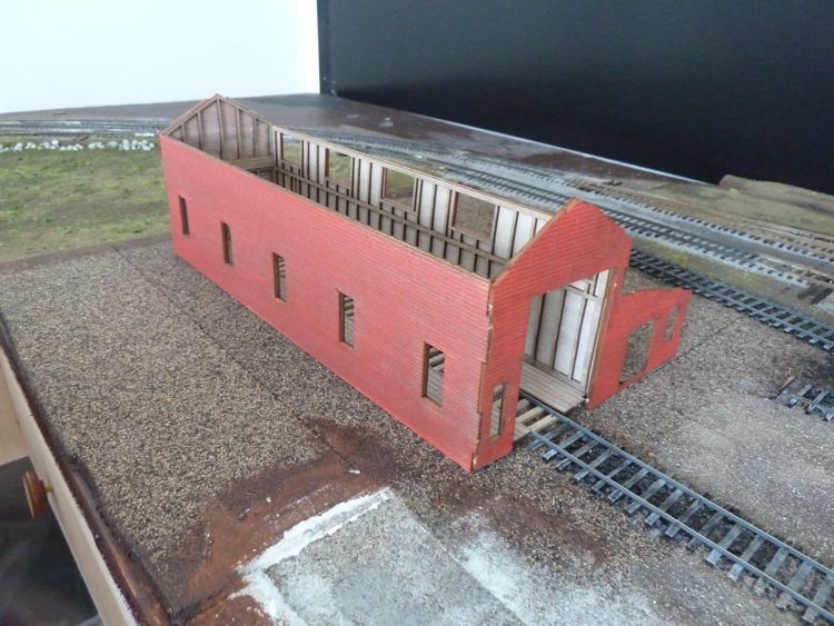
Up close, I can see lots of things that make me a bit unhappy, like that join in the upper right corner. I could of swore that was tighter. Overall though, it's coming together, and I do like the effect of the nails on the siding, and the stained look of the wood.
I realize that crayon is somewhat misleading, this is an artists oil pastel crayon. I can't tell you the brand, as it was the only one of that color left, and it was broken. I thought the shade would be right, and so far I'm pleased with the color.
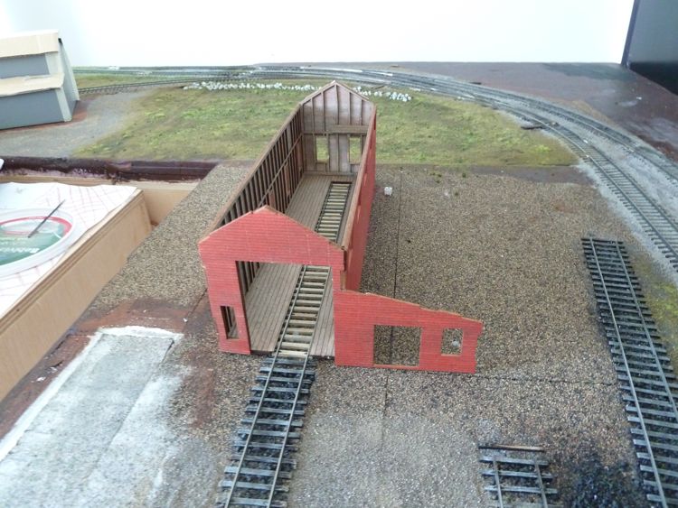
I put in the windows on the Engine House, but I'm not sure on the white tone. I've been trying to create a somewhat worn but still maintained look to the structure, but to my eye, the white of the windows looks almost too gray to my eye.
I may have to run another light coat of pure white over these.
I should describe how I painted them. I put a heavy dry brushed coat of Polly Scale aged white first, than a coat of craft store white on top. I wonder if the coat of aged white wasn't strong enough to hide the wood underneath.
No ink wash after the dry brush, but all parts in the kit got that prior to any other surface application.
I decided to just finish the windows and trim and see how it looks as a whole. I can easily go over it lightly with a small brush if needed (although it would be easier on the sprue).
Unfortunately, there was a lot of warping in the parts from the kit sitting in my basement in New Hampshire for a few years, and the shipment over seas in a very hot metal box during the humid season. In a lot of ways, I wish I had assembled this kit long before I moved, perhaps storing kits unbuilt is not the best way to preserve them.
For the record, the Branchline kits have (in my opinion) one of the best window systems I've put together, the way they do their clear glass, and the multi-window parts, is really nice to work with, due to a large part as there is no glue involved!
I got the trim up and the roof, well, roofed (it's loose, and not attached).
Still not near being done yet, I have to blend in some colors and spice up the foundation a bit, and of course, weather the roof, complete the chimneys, work on the interior, blah, blah, blah.
Scenery
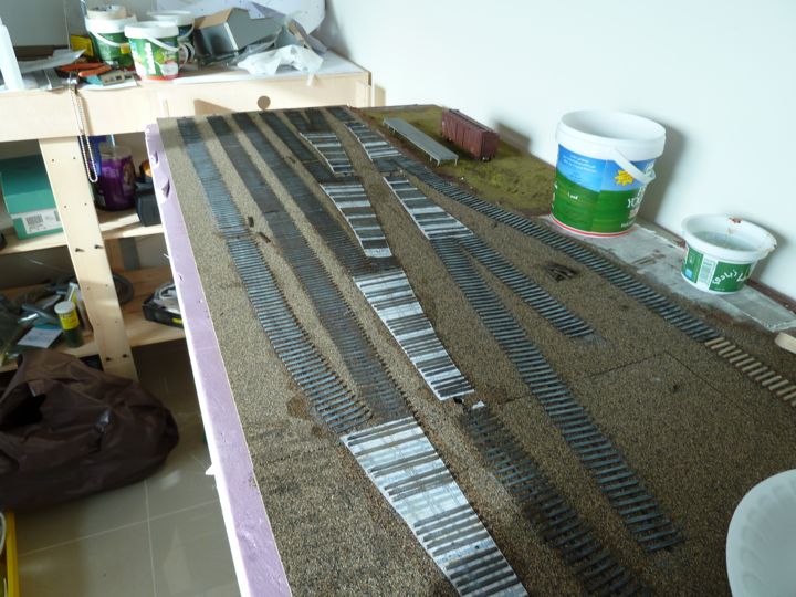
While putting down some grass on the fifth module, I came back to this one. Over a weekend, I was able to touch up all of the rail joiners with paint, ballast areas that I had skipped/missed, and of course, some static grass.
A long stretch between the caboose track and yard track, including a fair amount at the end of the caboose track. Not sure on what I'm doing around the engine house, but it's turn is coming up!
On my project list was to "sink" the rails into the dirt by raising the dirt around the track.
Sand, stain, and weathering powders has gotten it a lot closer to what I was envisioning.
I still need a lot more details, clutter, mess, plant life, etc in this scene, but with the base down, now that can begin.